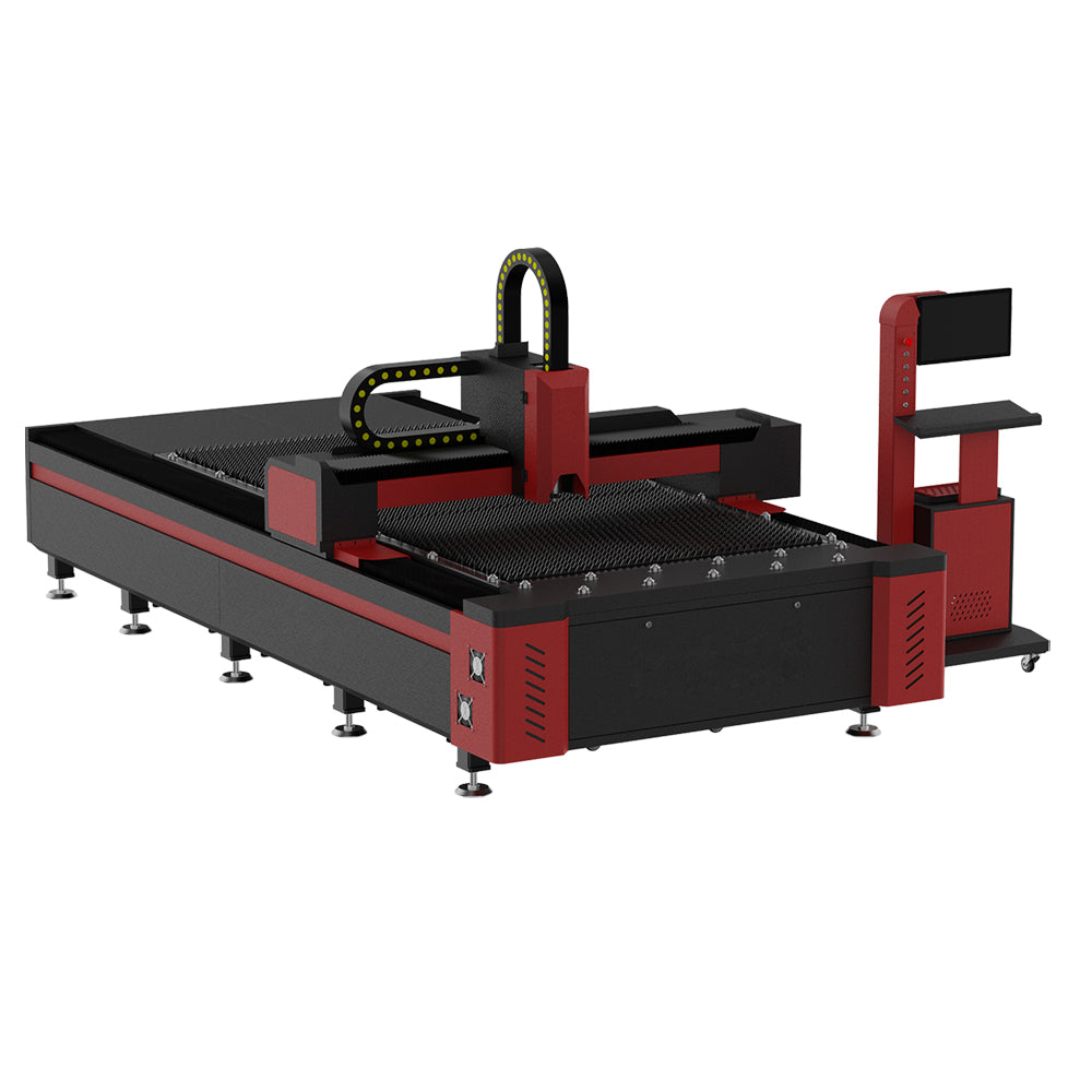
 3 kW Fiber Laser Cutting Machine
Metal additive manufacturing · SLM
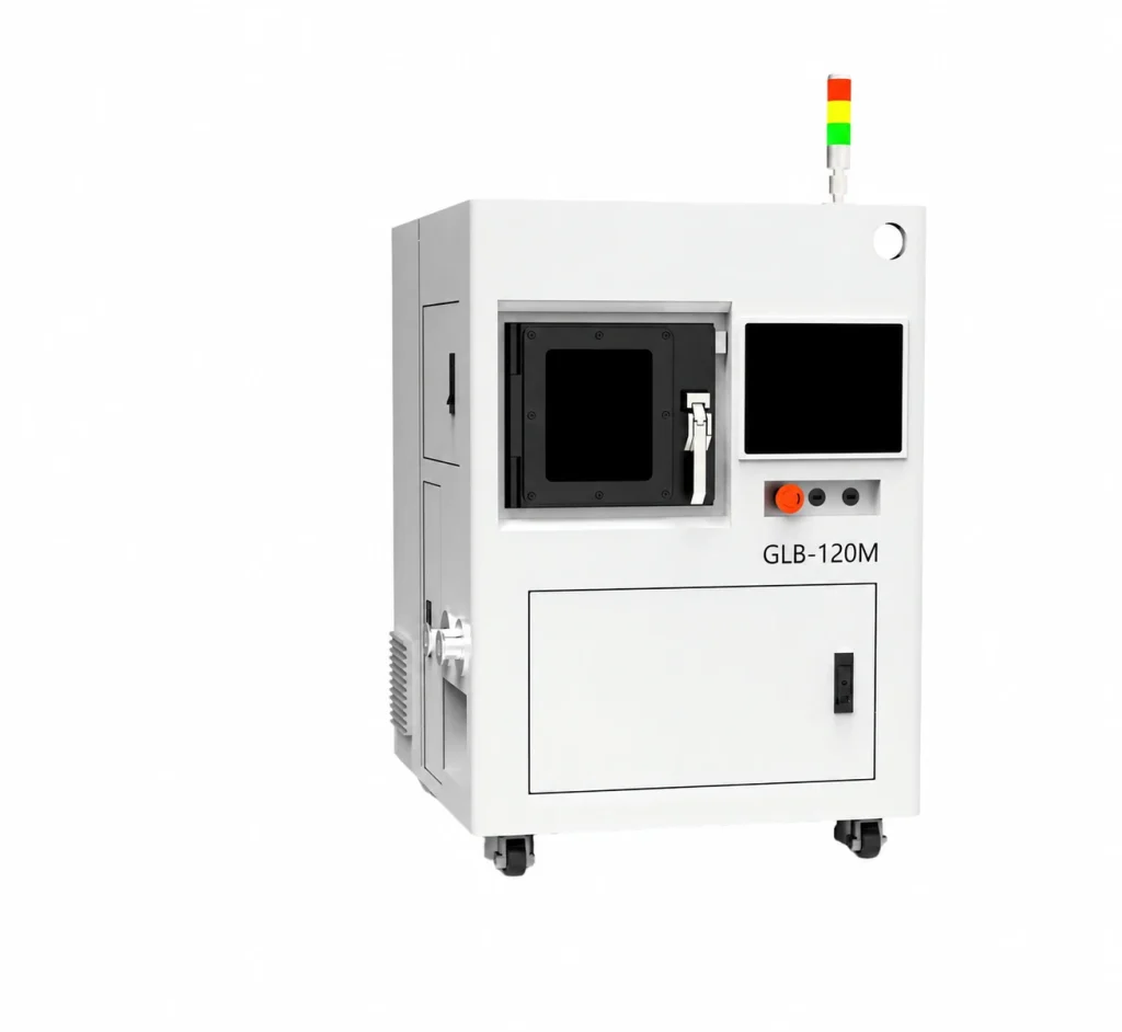
GLB-120M SLM Metal 3D Printer
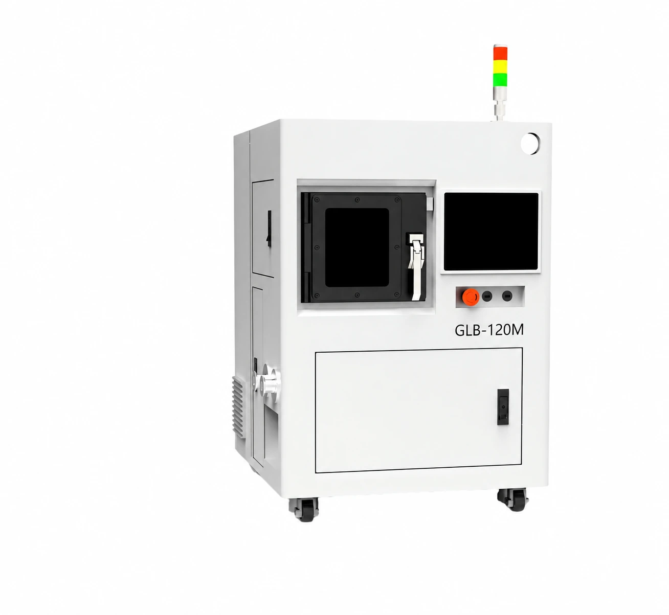
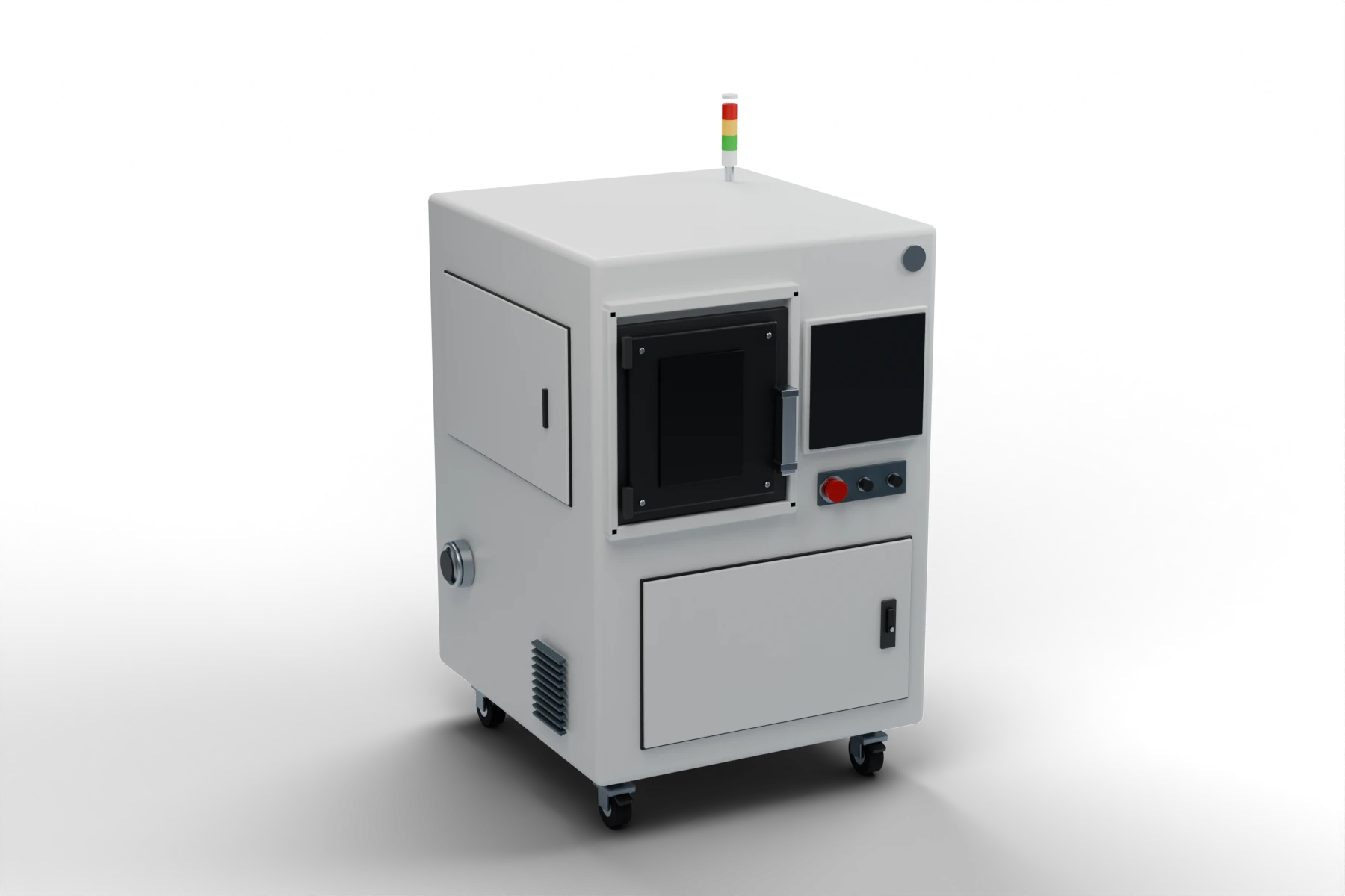
Product render · GLB-120-format equipment.
Blender exterior illustration. Refer to the supplied product render and confirmed configuration for equipment details.
Build metal geometry layer by layer with selective laser melting. Review your part model, powder material and finishing needs as one additive manufacturing workflow.
SLMSelective laser melting
Build configuration at a glance
- Build envelope
- Confirm the usable diameter and height for your part
- Nominal layer thickness (manual reference)
- 0.03 mm
- Protective gas options
- Argon / nitrogen, selected for the material
Send the overall part dimensions and material requirement to review the usable build space and process configuration.
SLM metal printing workflow.
Part preparation, powder handling and the build environment each contribute to the final metal component.
From model to build data
Prepare the part model and slicing data for the build. Review orientation, supports and the finishing allowance around the geometry you need.
Powder delivery and collection
The documented system includes powder spreading and collection. Match the powder specification and handling procedure to the selected material and equipment.
Controlled build environment
Protective gas and circulation form part of the machine workflow. Confirm the gas choice, site requirements and operating procedure for the material being processed.
GLB-120M technical reference.
Documented GLB-120M equipment references. Define the complete build, material and installation specification for the selected revision.
Find your configuration| Model | GLB-120M |
|---|---|
| Process | Selective laser melting (SLM) |
| Nominal layer thickness (manual reference) | 0.03 mm |
| Powder delivery | Top-up powder delivery system |
| Protective gas options | Argon / nitrogen, selected for the material |
| Machine dimensions and net weight | Confirm for the selected GLB-120M revision |
| Build envelope | Confirm the usable diameter and height for your part |
Confirm machine dimensions and net weight with a version-matched installation drawing. Also verify usable build diameter and height, laser configuration and qualified materials. Layer settings depend on the material and process.
Build space and geometry review
Provide the part model with overall dimensions and the intended orientation. Review usable build space, supports, separation from the plate and access for powder removal before accepting the layout.
Material and finishing scope
Specify the alloy or powder requirement and the final surface, fit and dimensional needs. Discuss material qualification, post-processing, inspection and operator training as part of the project scope.
Applications
Begin with the geometry you need.
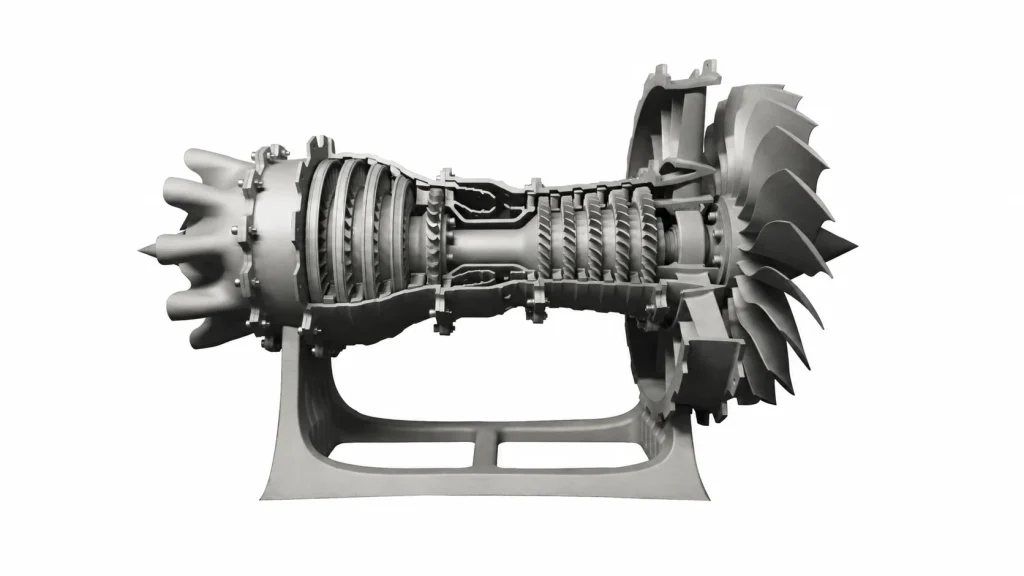
Explore forms, internal features and assemblies where an additive workflow may suit the design. Evaluate the part model together with the material, build orientation and finishing process.
Part development · Geometry studies · Small metal components
Discuss a sample test
Applications
Details continue beyond the build.
A small housing or watch-case geometry needs more than a printed shape. Include the required fit, surface finish and inspection points in the part brief so post-processing is considered from the start.
Discuss a sample testResources & support.
Prepare the part model and the manufacturing requirements together.
Before you choose.
What part size will fit?
Send the overall dimensions and intended build orientation. The usable build diameter and height must be confirmed for the selected equipment; the model name alone does not establish the build envelope.
Which metal powders can I use?
Provide the alloy or powder specification you require. Machine compatibility, process parameters, protective gas and powder handling are reviewed for the selected material.
Is the printed part ready for use?
A part may require separation, support removal, heat treatment, machining or surface finishing. Define the final dimensions and finish so the complete production and inspection route can be planned.
Get in touch
Let’s review your metal part.
Share the part model, overall size, material, quantity and final finish. We’ll help define the equipment and process review.
Email our team[email protected]Have a drawing or reference photo? Send it to us by email.
After your enquiry
Our team reviews your requirements and follows up on the machine configuration, sample arrangements or support you need.
Quotation checklist